Author(s): Simon Torry; Jack Whittaker ![]()

DOI: 10.14339/STO-J-02-02 | ISSN: TBD
Most in-service missiles have solid propellant rocket motors, the major component being the energetic propellant cast in an insulant-lined combustion chamber. The insulant is typically a solid-filled polymer that is thermally sacrificed during motor combustion. The reactivity of some propellant ingredients with typical rubber formulation components can limit insulant formulation.
Citation:
ABSTRACT
Most in-service missiles have solid propellant rocket motors, the major component being the energetic propellant cast in an insulant-lined combustion chamber. The insulant is typically a solid-filled polymer that is thermally sacrificed during motor combustion. The reactivity of some propellant ingredients with typical rubber formulation components can limit insulant formulation. The aim of this programme was to formulate effective barrier coatings suitable for application between the insulant and propellant that, if successful, could increase the range of materials that could be safely used in insulants and thereby improve their performance. A number of graphene and functionalised graphenes were investigated as to their suitability in binder systems that are known to be compatible (non-reactive) with composite and double base propellants. Although described as graphene and graphene oxide, some off-the-shelf materials were found to consist of thick flakes (assessed by optical and scanning electron microscopy) that proved difficult to exfoliate by both ultrasound and acoustic mixing. The graphene samples were unable to form stable colloids in typical graphene “solvents” (as measured using visible spectroscopy). Even materials that did form stable solutions were found, using an optical microscope, to consist of thick particles as opposed to single or multilayer graphene sheets (with less than ten layers). An alkylamine functionalised graphene oxide dispersion was found to contain sheets of material that were flexible and transparent suggesting this material had stable graphene-like dimensions. The alkylamine functionalised graphene oxide was added to two families of binders – single component binders crosslinked at 120°C and two component binders crosslinked at 95°C. Traditional “drying” agents, such as zinc caprylate, were found to be not beneficial for creating an even graphene coating on glass microscope slides. Insulant samples (silica / carbon fibre filled Polyvinylchloride/Nitrile (PVC/NBR) or Ethylene-co-Propylene Diene Monomer (EPDM) rubber) coated on one side with test barrier coating were soaked in bis-(2-ethyl hexyl)adipate (DOA) / polybutadiene solutions at 50°C, over five days, to test barrier efficacy. Samples were cross- sectioned using a microtome and the extent of diffusion of the DOA plasticiser into the insulant was measured using an infrared microscope. Samples coated (one to three coats) with the one component binders at a binder to graphene additive ratio of 1:1 were ineffective barriers. The two component binder systems, at ratios of functionalised graphene to binder of 1:3 or 1:4, were found to be effective barrier coats to DOA diffusion. Eight barrier coats, totalling approximately 0.015 mm thick, were found to decrease the amount of DOA at the insulant surface by more than 95%.
1.0 INTRODUCTION
Graphene and the family of functionalised graphenes, have potential to being beneficial in energetic materials and other materials such as adhesives and insulants used in rocket motors, by exploiting graphenes’ chemistry, topology and electrical properties. In the case of energetic composites, there is a potential for graphene to:
- improve ballistic performance by catalysing and controlling how a propellant burns
- improve thermal conductivity lowering thermal hazard effects of energetic materials
- improve mechanical properties of explosives and propellants
- decrease sensitivity to electrostatic hazards
- stabilise energetic molecules in host structures
- decrease sensitiveness to mechanical impact
- control migration of energetic molecules via barrier properties.
Energetic materials are often used in weapon sub-systems, for example solid rocket motors. Undesirable interactions can occur during their service life. This can be a particular problem when low molecular weight species migrate from their original position potentially causing degradation of adjacent components, decrease liner-propellant bond strength and cause potential system failure. This could be mitigated if there were an effective barrier between components.
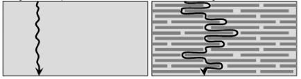
Figure 1: Diffusion through self-assembled graphene sheets. Normal diffusion (left), impeded diffusion through graphene (right).
A number of barrier coatings based on high aspect ratio nanocomposites such as vermiculite in latex [1], polymer/layered silicates [2], multi-walled carbon nanotubes, modified layered-silicates, polyhedral oligomeric silsesquioxanes [3], nano-metal oxides, nano-glass flakes, nano-nitrides [4] have been developed and can decrease gas permeability 20 to 30 fold [1]. For energetic applications, it is desirable to use fillers with little reactivity towards nitrate esters and other energetic moieties, hence in this work, carbon based materials were considered as fillers in a barrier formulation. Carbon is commonly used as an additive in energetic materials (as a ballistic modifier and in low friction coatings). Although carbon black has been used in barrier applications, Christopher et al. [5] found that graphene fillers outperformed carbon black in corrosion barrier applications. Similarly, Yang et al. [6] found that plate-like fillers were superior to carbon black in nitrile butyl rubber barrier applications. Due to its high aspect ratio and high electron density in its aryl ring structure, graphene has a reputation of being a good barrier towards even small atoms such as helium [7][8]. The permeability towards gases and other molecules depends on the defects in the graphene, how the graphene sheets assemble into macrostructures and how well the graphene is dispersed and orientated. It is thought that multilayer graphene sheets should impede diffusion by increasing the tortuosity and diffusant pathlength. Some workers have found that addition of graphene to polymers induces the polymer to crystallise thereby decreasing the more permeable amorphous content [9].
The aim of this work was to investigate the use of graphene as a barrier to prevent or impede the diffusion of DOA plasticiser into a rocket motor insulant. Self-assembling of the graphene into flat sheets would effectively increase the diffusion pathway of the plasticiser (as per Figure 1) and hence limit plasticiser migration.
2.0 EXPERIMENTAL
2.1 Binders
Binders (hydroxy terminated polybutadiene (HTPB), Cray Valley; polyvinyl butyral, Sigma-Aldrich; polyvinylformal, Sigma-Aldrich; polycaprolactone, Perstorp) were dried before use in a vacuum, overnight at 60°C. Crosslinker species (isophorone diisocyanate IPDI, Sigma-Aldrich; Isocyanate N3600, Bayer; epoxy, Momentive) were used as received. Insulants were proprietary formulations based on ethylene-co-propylene diene monomer (EPDM) and polyvinylchloride/nitrile (PVC/NBR).
2.1 Graphene Samples
The five graphene and graphene oxide samples, used in this programme, are summarised in Table 1. Three samples were solid powders, whilst the alkylamine functionalised graphene oxide, and graphene dispersion were supplied in solvent.
Table 1: Graphene sources.
|
Sample |
Source |
|
Elicarb Materials Grade Graphene Powder |
Thomas Swan, County Durham |
|
Graphene oxide |
Sigma Aldrich, 763713-1G |
|
Graphene oxide, alkylamine functionalised 2 mg per cm3 in toluene |
Sigma Aldrich, 809055-50ML |
|
Graphene oxide powder, 15-20 layers, 4-10% edge-oxidized (Aldrich) |
Sigma Aldrich, 796034-1G |
|
10 mg/mL, graphene dispersion in N-methyl-2-pyrrolidone (NMP) |
Sigma Aldrich, 803839-5ML |
|
Graphene ink C2131121D3 |
Gwent Group |
Within a week of receipt, the graphene in NMP solvent settled out of solution – application of low power ultrasound did not disperse the graphene into a stable colloid. There appeared to be no visible change in the alkylamine functionalised graphene oxide dispersion in toluene over a period of at least three months. Throughout the programme, it remained as a stable, pale brown dispersion slightly more viscous than pure toluene. Most exfoliation work was performed on the Elicarb graphene. For comparison, other graphene samples were investigated.
2.2 Spectroscopy
Fourier transform infrared (FTIR) measurements were performed using a Nicolet iS50 spectrometer fitted with an inbuilt diamond attenuated total reflection (ATR) detector. Infrared mapping experiments were performed using a Nicolet iN10 FTIR microscope in transmission mode (ultrafast mode, 150 x 20 µm step size and 150 x 20 µm aperture) at a spectral resolution of 16 cm-1. Raman spectroscopy was collected using an iS50 Raman Module with a 1064 nm laser (variable power up to 0.5 W) with a 50 µm spot size.
Visible spectroscopy was performed using matched 10 mm silica cuvettes in a Perkin Elmer Lambda 20 spectrometer. An absorption measurement was performed every ten seconds over a period of ten hours.
Nuclear magnetic resonance (NMR) measurements were performed using a Bruker Avance 400 spectrometer (proton frequency 400 MHz) fitted with a 5 mm quattro nucleus probe. Samples were dissolved in deuterated dimethyl formamide (DMF) and proton spectra measured at 25°C.
2.3 Microscopy
Microscopy was performed using a Zeiss AxioImager A1m microscope in transmitted or reflected light modes (2.5 to 50 times magnification). Image analysis was conducted using the AutoMeasure Plus module in the microscope’s Zeiss AxioVision 4.6 software.
Scanning electron microscopy (SEM) was carried out using a Hitachi S-3500N Electron Microscope and an Oxford instruments X-Max50 EDX with Aztec software. Samples were mounted onto stubs coated with conductive adhesive tape.
2.4 Graphene Dispersion
Two methods of exfoliation were attempted in this work:
- • Acoustic mixing
- • Ultrasound bath
Acoustic mixing was performed using a Resodyn LabRAM acoustic mixer fitted with a bespoke polycarbonate vial holder. Samples were mixed in disposable 10 ml glass vials fitted with PTFE faced screw tops. The mixer’s power input and mixing time were varied in an attempt to improve exfoliation and dispersion.
Attempts were made to disperse graphene samples in solvents (1 mg per cm3) in an ultrasound bath (200 to 400 W), at room temperature for up to two hours.
2.4 Plasticiser Diffusion in Insulant
The alkylamine functionalised graphene oxide was provided as 2 mg/cm3 in toluene. The dispersion was further diluted with the binder system in THF (dried over 4A molecular sieve). Rocket motor insulant plaques (6 mm x 12 mm x 19 mm) were coated on one side with the barrier coating solution as per Figure 2.
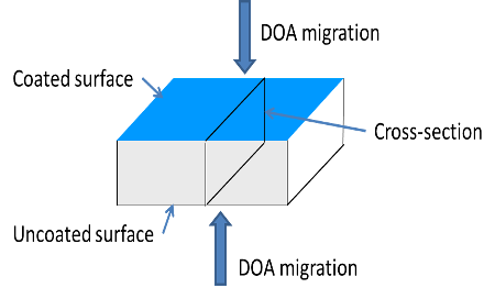
Figure 2: Insulant plaque configuration.
Solution was dripped onto the surface using a pipette (typically 3 drops per 2.2 cm2 surface). The solvent was allowed to evaporate and a further three drops were applied to the surface. The surface was then allowed to cure at temperature for a known amount of time. If required the sample was recoated.
The barrier efficacy was assessed by soaking the coated insulant plaque in a polymer/plasticiser solution (46% bis-(2-ethylhexyl) adipate (DOA), 53% HTPB, 1% antioxidant) for up to five days at 50°C. After ageing, the samples were patted dry using tissue paper. The centre portion of the plaque was cut out and sectioned to a thickness of 25 and 30 µm using a Bright cryogenic microtome at -36°C using a tungsten carbide knife set at an angle of 23°. The insulant centre slice was mounted between sodium chloride plates. Infrared microscopy was used to assess the relative DOA concentration by measuring the carbonyl peak area at 1739 cm-1 through the plaque cross-section.
3.0 RESULTS
3.1 Graphene Characterisation
Attempts were made to characterise the graphenes using diamond ATR infrared and Raman spectroscopy. Additionally, optical and SEM microscopy was performed on the samples.

Figure 3: ATR IR of alkylamine functionalised graphene oxide. Top - as received, middle - dried for five minutes, bottom - dried for 1.75 hours.
The ATR IR spectra of the solid graphenes/graphene oxides were mostly featureless. The Elicarb and graphene oxide 1-20 sheets were broad band IR absorber. The graphene oxide was in the form of thick, large (~1 to 5 mm2) sheets. Its IR spectrum exhibited OH stretches, and carboxylic acid signals. Broad signals around 1500 to 1000 cm-1 are thought to be in part due to polyaromatic species.
IR measurements of alkylamine functionalised graphene in toluene (Figure 3) indicated that toluene was still in the sample after 1.75 hours drying (as indicated by the peaks at 1494, 752 and 693 cm-1). The IR suggested that as well as alkyl species (2922, 2855, 1465 cm-1), carboxylates (1740 to 1600 cm-1) and polyaromatic species (1450-895 cm-1) are present. These signals are also observed in the Sigma Aldrich graphene oxide.
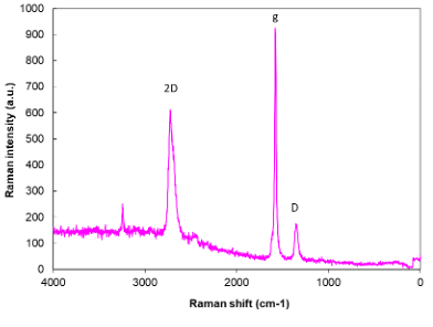
Figure 4: Raman of Elicarb graphene.
Attempts were made to measure the Raman spectra of the graphene samples using a near infrared (1064 nm) laser.
The laser power was altered from 0.05 to 0.5 W, and the number of scans was increased in attempt to measure a structural spectrum. The Elicarb sample did not exhibit the normal graphene signals using 1064 nm excitation. The spectra generally consisted of a broadband emission peak at 3400 cm-1 and other minor peaks. The graphene sample spectra were similar to carbon black signals.
Measurements were also performed on the same material using a 532 cm-1 laser [10]. The Raman spectrum consisted of 2D, g and D peaks (Figure 4). The ratio of the 2D/g peak areas indicated that the material consists of graphene structures (D/G ratio of 0.087). According to the manufacturers, Elicarb graphene materials grade should have a D/G ratio of typically 0.07 to 0.1 and consist of a “few layers” graphene platelets of 5 µm lateral size.
The Raman spectrum of alkylamine functionalised graphene oxide consisted of broad humps at 3500, 1800 to 1000 and 900 to 100 cm-1. These are probably associated with OH and carboxylic acid groups decorating the graphene surface.
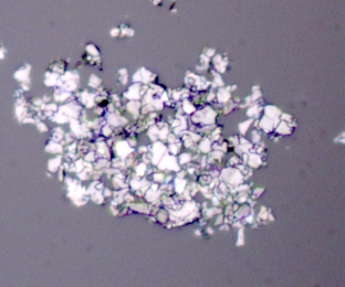
Figure 5: Optical micrograph of Elicarb graphene.
Unless careful surface preparation is performed on slides with optimised refractive indices, single layer graphene sheets are nominally invisible to optical microscopy measurements [11,12,13]. As no surface preparation was performed on the optical slides used in this work, the observation of visible flakes was used as evidence for multilayer graphene/graphite. The Elicarb graphene powder consisted of agglomerates and flakes (Figure 5 ). The graphene oxide consisted of large flakes (several mm2) with smooth surfaces. The graphene oxide 15-20 layers consisted of very small particles and loose agglomerates.
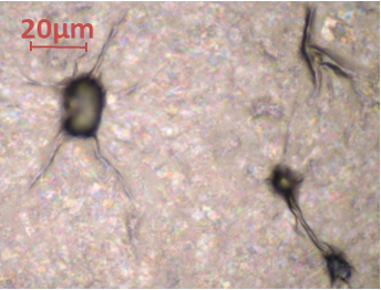
Figure 6: Optical micrograph of amine functionalised graphene oxide.
Upon drying, the graphene dispersed in NMP consisted of visible flakes whilst the as received alkylamine functionalised graphene oxide was nominally invisible under the microscope. Folds around particles and other unfocused features (Figure 6 ) were observed. Some thicker flakes were observed – they exhibited interference bands which suggest that some of the flakes have thicknesses of the order of 100 to 400 nm.
The samples were subjected to SEM and EDX measurements to assess morphology and carbon to oxygen ratio. The solid Thomas Swan Elicarb graphene appeared to be a free-flowing fine powder. The graphene was built up to a thickness which would prevent the electron beam interacting with the mounting tab. At a low magnification, the graphene was found to be agglomerated. At higher magnifications, using the SE detector, small sections of graphene, appearing to be semi-transparent to the electron beam due to the thin layers of atoms (e.g. Figure 7 highlighted by green circle).
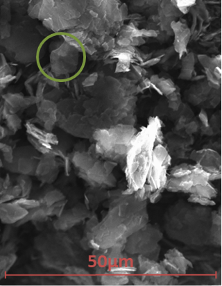
Figure 7: SEM micrograph of Elicarb.
EDX analysis indicated 96.8% carbon with 3.0% oxygen and copper and sodium impurities at 0.1% each. Graphene dispersion behaviour is thought, in part, to be a function of the C/O ratio.
Graphene oxide and graphene oxide (15-20 layers) contained 4.9 and 14.8% oxygen, respectively. Graphene from NMP and functionalised graphene oxide could not be deposited in a thick enough layer to measure the oxygen content reliably. As in optical observations, SEM microscopy of amine functionalised graphene oxide did not observe individual sheets but did observe folds and creases of material around occluded particles.
3.2 Graphene Exfoliation and Deposition
The process of exfoliating solid graphene/graphite into graphene sheets requires the use of solvents that interact well with the graphene surface. Traditionally, solvents such as DMF, NMP, and isopropanol have been used to form stable graphene dispersions. Such solvents interact with the graphene surface in such a way as to prevent the graphene sheets reassembling into graphite. These solvents tend to have high boiling points or functional groups that are potentially reactive with typical binder systems. In this work, solubility parameters have been used to assess potential, non-reactive, solvents that interact well with graphene forming a stable solution and that could also flash off after coating a surface (causing graphene deposition). According to the Hansen solubility parameter method [14], solvents such as cyclohexanone, THF, NMP and 1,3-dioxalane are expected to interact well with graphene (Table 2).
Low “R” numbers (calculated as per equation 1) indicate good interaction between the solvent and graphene. Solvents such as water, ethanol and methanol are expected to act as bad dispersion solvents. The degree of solvent interaction will depend on the nature of the graphene. If the graphene is oxidised then the Hansen parameters will be different, and the family of dispersion solvents will also change. It is noted that although graphene is poorly dispersed in water, graphene oxides are well dispersed in water. Most of the exfoliation work was carried out using Elicarb Materials Grade Graphene Powder. As the stable dispersion mass level per unit volume of solvent was unknown, all solutions were prepared at a concentration of 1 mg per cm3 of solvent. In this work, two methods of exfoliation were studied: 1) acoustic mixing (medium shear mixing technique) and 2) ultrasound (200 to 400 W).
The rate of graphene falling out of solution for some samples was assessed by following the change in absorption at 660 nm using a visible light spectrometer [15]. Sample solutions were deposited onto microscope slides to assess whether the processing had exfoliated the sample to “invisible” graphene sheets. It was assumed that if the graphene was fully exfoliated then the broken down aggregates would form graphene sheets that would be invisible under an optical microscope. Only thick layers would be observed.
Table 2: Solubility parameters [16].
|
Material / Solvent |
Boiling Point / °C |
∆∂d /MPa0.5 |
∆∂p /MPa0.5 |
∆∂h /MPa0.5 |
R |
|
Graphene [17] |
- |
18 |
9.3 |
7.7 |
- |
|
Cyclohexanone |
155.6 |
17.8 |
8.4 |
5.1 |
2.78 |
|
Methylene chloride |
39.6 |
17 |
7.3 |
7.1 |
2.89 |
|
NMP |
202 |
18 |
12.3 |
7.2 |
3.04 |
|
1,3-Dioxolane |
75 |
18.1 |
6.6 |
9.3 |
3.14 |
|
Acetone |
56 |
15.5 |
10.4 |
7 |
5.16 |
|
N,N-Dimethyl acetamide |
165 |
16.8 |
11.5 |
10.2 |
4.10 |
|
Tetrahydrofuran |
66 |
16.8 |
5.7 |
8 |
4.34 |
|
Methyl propyl ketone |
101 |
16 |
7.6 |
4.7 |
4.78 |
|
Acetonitrile |
81 |
16 |
12.8 |
6.8 |
5.39 |
|
Methyl acetate |
57.1 |
15.5 |
7.2 |
7.6 |
5.42 |
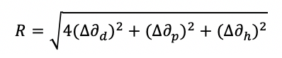
Where ∆∂d, ∆∂p, ∆∂h, are the difference between the graphene and solvent dispersion (∂d), polar (∂p), and hydrogen bonding (∂h) solubility parameters.
Although high mixer input powers and extended mixing times were employed, acoustic mixing processing could only break down the Elicarb aggregates to visible sheet-like particles. These particles shimmered in solvent when shaken. This suggested the acoustic mixing could not exfoliate Elicarb to graphene sheets.
Ultrasound was also used in an attempt to exfoliate Elicarb and other graphenes to form stable colloids. In this work, UV-Vis spectroscopy was used to see how stable the graphene colloid was. Samples of graphene exfoliated by acoustic mixing or ultrasound were left in a UV-Vis cuvette overnight. For most samples, the graphene precipitated out of the solution within 1.5 hours (Figure 8) to concentrations between 0.025 to 0.075 mg per cm3.
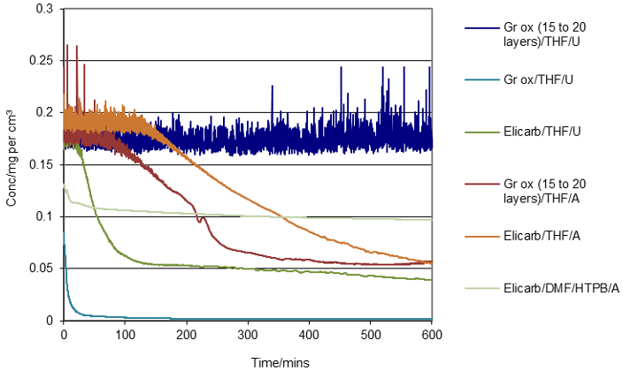
Figure 8: UV assessment of some graphene/graphene oxide stability in solvents and additives. A = acoustic mixing exfoliation, U = ultrasound exfoliation.
Most of the Elicarb samples were unstable in THF or DMF (processed using ultrasound or acoustic mixer). Addition of polymer (Butvar) and surfactants (Zn caprylate, Zn neodecanoate) appeared to stabilise the Elicarb sample to some extent (taking from 340 to 480 minutes to reach 0.1 mg per cm3). The graphene oxide (15 to 20 layers) appeared to be stable for at least ten hours post ultrasound processing. Similar solutions left on the bench appeared to be visibly stable for more than eight weeks. Graphene oxide (15 to 20 layers) processed using acoustic mixing was less stable than the equivalent ultrasound processed material.
Graphene solutions were deposited onto glass microscope slides to assess whether the exfoliation process and the use of additives facilitated the exfoliation and even deposition of graphene over the slide surface. Zirconium (IV) 2-ethylhexanoate, zinc neodecanoate, zinc caprylate and zinc stearate surfactant additives with and without polybutadiene or Butvar did not facilitate the even distribution of graphene layers on the slide.
Higher ultrasound powers and alternative shear mixing techniques may be more suitable for exfoliating the graphene powders. However, in this work the only material that evenly coated the slide was alkylamine functionalised graphene oxide (surfactants did not improve the coating ability of the graphene oxide).
3.3 Curing Reactions With/Without Graphene
Alkylamine functionalised graphene oxide fulfilled the criteria of fully coating a rough surface (observation of folds around surface particles). Hence alkylamine functionalised graphene oxide was used in barrier coating formulations. Two types of binder systems were considered for coating formulations: 1) high temperature crosslinking one component systems, and 2) low temperature crosslinking two component systems. The high temperature processes, although nominally poorly controlled, are simple reaction processes. These were originally considered as good binder candidates as it was thought that extraneous reactions were less likely to occur. The two component crosslinking reactions in this work (epoxy ring opening and isocyanate reactions) are sensitive to moisture. This is especially an issue using dilute solutions/solvents that have to be employed when handling graphene dispersions. Graphenes are only stable in dispersions at low concentrations. Care was taken to ensure solvents were dry for use. Excess curative (typically 10%) was used in case solutions were contaminated with water. None of the crosslinking processes have been optimised with respect to curing ratio, additives, temperature etc. These are scoping reactions to see if the binder systems facilitate the coating of graphene onto uneven rubber surfaces.
The effect of alkylamine functionalised graphene oxide on the curatives and crosslinking processes were assessed by mixing amine functionalised graphene oxide with the binder system, casting the sample onto a silicon plate, measuring the IR spectrum, heating the sample at a known temperature and time, and measuring the change in the IR spectrum. As the graphene has a large surface area and is decorated with a number of unknown functionalities, there is potential for the graphene to interfere with the binder crosslinking process.
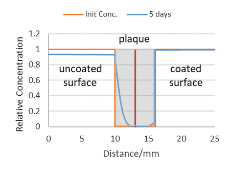
Figure 9: Theoretical profile of DOA diffusing into coated (right) and uncoated (left) plaque surfaces. Grey area = plaque cross-section.
Eight binder systems were investigated at elevated temperatures (95 to 120°C): 1) polybutadiene oxidisation, 2) isocyanate oligomerisation and reaction with ambient moisture, 3) epoxy ring opening by moisture and catalysts, 4) polyvinyl butyral transacetalisation, 5) polyvinyl formal transacetalisation, 6) hydroxyl terminated polybutadiene (HTPB)/isocyanate urethane formation, 7) polycaprolactone/isocyanate urethane formation, and 8) epoxy/butanediol/catalyst ring opening.
There was qualitative evidence that the alkylamine functionalised graphene oxide did not affect polybutadiene oxidation. The functionalised graphene oxide may have impeded isophorone diisocyanate oligomerisation and may have reacted with isocyanate Desmodur N3600 (hexamethylene diisocyanate isocyanurate). It was difficult to observe transacetalization in polyvinyl formal and polyvinyl butyral and the effect of amine functionalised graphene oxide. It proved difficult to observe epoxy ring opening and any effect of the graphene oxide. Isocyanate N3600 and IPDI readily reacted with HTPB or polycaprolactone in the presence of alkylamine functionalised graphene.
3.4 Coated Insulants and Diffusion
Assuming the diffusion processes are Fickian in nature and that DOA is mutually soluble in all the materials, then the diffusion profile could be modelled by:
- Coated surface. DOA diffusing from solution to the barrier coating surface (diffusion coefficient Ds). DOA diffusing through a thin layer of barrier coating into the polymer plaque (diffusion coefficient Db). DOA diffusing into the polymer plaque (diffusion coefficient Dp).
- Uncoated surface. DOA diffusing from solution to the polymer plaque surface (diffusion coefficient Ds). DOA diffusing into the polymer plaque (diffusion coefficient Dp).
- Initial conc. = 1 in solution, Initial conc. = 0 in barrier and plaque. Rate at which DOA leaves solution = rate at which it enters interfaces. DOA solution Ds = 1·e-5 cm2 s-1. Barrier coating at 10 mm; 0.05 mm thick, Db = 5·e-11 cm2 s-1. Plaque at 10.05 mm to 16.05 mm, Dp = 1·e-8 cm2 s-1.
Figure 9 illustrates a predicted DOA diffusion profile, calculated using the PDE functionality in MatLab, of a plaque with a good barrier coating on one surface (right side of plaque cross-section) and no coating on the right hand plaque surface. The initial DOA concentration profile (orange line) is predicted to evolve an unsymmetrical profile in the presence of an effective barrier coating.
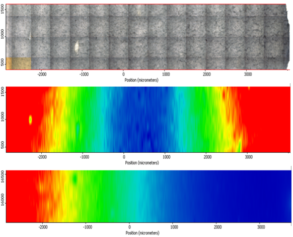
Figure 10: DOA distribution, barrier coating right hand side – composite optical micrograph (top), IR map of poor barrier coating (middle), IR map of good barrier coating (bottom). Hot colours (red, orange, yellow) = high concentration of DOA. Cold colours (green, cyan, blue) = low concentration of DOA.
The predicted plaque DOA profile compares well with the measured profile of a insulant coated with a good barrier. Typical IR maps of plaques with a poor barrier coat and a good barrier coat for EPDM insulants are illustrated in Figure 10. The bottom contour map in Figure 10 indicates the DOA readily migrates through the uncoated surface, but plasticiser migration (right hand side) is impeded through the coated surface.
Microtome slices can be of uneven thickness and therefore alter the apparent peak intensity of the DOA. Variation in carbonyl content due to sample thickness was avoided by calculating the ratio of the DOA carbonyl peak height at 1739 cm-1 against a polymer/insulant peak that was independent of DOA spectral features (peak height at 3323 cm-1). Six DOA profiles (Figure 11) overlay each other reasonably well. The profiles are relatively “noisy” as each spectrum samples a volume that contains areas of impermeable fibre.
The ratio of the DOA peak concentration at the uncoated surface relative to the coated surface was used as a metric for barrier efficacy (DOA surface ratio). Additionally, in the case of DOA absorbed in PVC/NBR insulant, the centre baseline value subtracted from both edge values before calculating the DOA surface ratio.
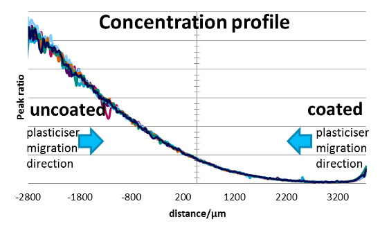
Figure 11: Profile plot of DOA distribution in 8x coated EPDM.
None of the single component binder systems exhibited good barrier properties (1:1 binder to graphene composition). Even samples with three coats exhibited poor barrier coating efficacy – the lowest DOA surface ratio was 0.81.
Two component binder systems with higher binder content performed much better as barrier coatings. In the absence of graphene, the binder systems did not appear to impede DOA diffusion to any significant extent into the insulants. Hence the presence of graphene was critical to the barrier efficacy of the tested coatings. The barrier efficacy depended on the number of applied coats (Figure 12). Eight barrier coats in on EPDM insulant decreased the DOA surface ratio to below 0.05. That is to say the permeability has decreased by at least 95%. A plaque with eight coats is thought to have approximately 1.3 mg of binder/graphene per cm2 surface. Assuming the density of the graphene/binder is 0.9 g per cm3, this would mean the barrier coating is approximately 0.015 mm thick.
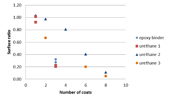
Figure 12: DOA surface ratio versus number of coats (two-part binder systems) on EPDM insulant.
4.0 Summary and Conclusions
The aim of this programme was to investigate and formulate effective barrier coatings suitable for application between the insulant and propellant that, if successful, could increase the range of materials that could be safely used in insulants and thereby improve their performance.
A number of graphene and functionalised graphenes were investigated as to their suitability in binder systems that were known to be compatible (non-reactive) with composite and double- base propellants. It proved difficult to exfoliate by both ultrasound and acoustic mixing (high shear) some graphene materials. The graphene samples were unable to form stable colloids in typical graphene “solvents”. Even materials that did form stable solutions were found, using an optical microscope, to consist of thick particles as opposed to single or multilayer graphene sheets (with less than ten layers). Although the graphene and graphene oxides used in this work exhibited characteristics that are associated with graphenes, most materials proved not to be suitable as a coating component. An alkylamine functionalised graphene oxide (2 mg per cm3 in toluene) was found to contain sheets of material that were flexible and transparent suggesting this material had stable graphene-like dimensions.
The alkylamine functionalised graphene oxide was added to two families of binders – single component binders crosslinked at 120°C and two components binders crosslinked at 95°C. Traditional surfactant agents such as zinc caprylate were found not to be beneficial for creating an even graphene coating on glass microscope slides. Insulant samples (PVC/NBR or EPDM rubbers) coated on one side with test barrier coating were soaked in dioctyl adipate/polybutadiene solutions at 50°C to test barrier efficacy. Samples coated (one to three coats) with the one component binders at a binder to graphene additive ratio of 1:1 were ineffective barriers.
The two component binder systems, at ratios of alkylamine functionalised graphene to binder of 1:3 or 1:4, were found to be effective barrier coats to DOA diffusion. Eight barrier coats, totalling approximately 0.015 mm thick, were found to decrease the amount of DOA at the insulant surface by more than 95%.
For future work, the binder formulations should be optimised with respect curing ratio, additives, and cure temperature. Better control of surface coverage, both homogeneity and applied mass, should be investigated. The binder to graphene ratio and graphene concentration should be optimised. Other bespoke functionalised graphenes should be synthesised and investigated in an attempt to increase the concentration of stable functionalised graphene dispersion. Application methodologies, such as spraying, should be investigated.
REFERENCES
[1] S. Takahashi, H.A. Goldberg, C.A. Feeney, D.P. Karim, M. Farrell, K. O’Leary, D.R. Paul, Gas barrier properties of butyl rubber/vermiculite nanocomposite coatings, Polymer, 47, 3083–3093, 2006.
[2] Jui-Ming Yeh, Kung-Chin Chang, Polymer/layered silicate nanocomposite anticorrosive coatings, Journal of Industrial and Engineering Chemistry, 14, 275–291, 2008.
[3] M. Joshi, B. Adak, B.S. Butola, Polyurethane nanocomposite based gas barrier films, membranes and coatings: A review on synthesis, characterization and potential applications, Progress in Materials Science, 97, 230–282, 2018.
[4] S. Pourhashem, F. Saba, J. Duan, A. Rashidi, F. Guan, E. G. Nezhad, B. Hou, Polymer/Inorganic Nanocomposite Coatings with Superior Corrosion Protection Performance: A Review, Journal of Industrial and Engineering Chemistry (2020), doi: https://doi.org/10.1016/j.jiec.2020.04.029.
[5] G. Christopher, M. Anbu Kulandainathan, G. Harichandran, Comparative study of effect of corrosion on mild steel with waterborne polyurethane dispersion containing graphene oxide versus carbon black nanocomposites, Progress in Organic Coatings 89, 199–211, 2015.
[6] X. Yang, L. K. A. Schneider, U. Giese, R. H. Schuster, Characterization of Permeability of Elastomers Part II, 63(11), 496-505, 2010.
[7] M. J. Nine, M. A. Cole, D. N. H. Tran, D. Losic, Graphene: a multipurpose material for protective coatings, J. Mater. Chem. A, 3, 12580–12602, 2015.
[8] Y. Cui, S. I. Kundalwal, S. Kumar, Gas Barrier Performance of Graphene/Polymer Nanocomposites, Carbon, 98, 313–333, 2016.
[9] A. Al‐Jabareen, H. Al‐Bustami, H. Harel, G. Marom, Improving the oxygen barrier properties of polyethylene terephthalate by graphite nanoplatelets, Journal of Applied Polymer Science, 128 (3), 1534-1539, 2013.
[10] C. Baker, R West, email communication, QinetiQ, 21/10/2016, 0937.
[11] R. Zan, Q. M. Ramasse, R. Jalil, U. Bangert, Atomic Structure of Graphene and h-BN Layers and Their Interactions with Metals, Nanotechnology and Nanomaterials, "Advances in Graphene Science", IntechOpen Ltd, Mahmood Aliofkhazraei (ed.), ISBN 978-953-51-1182-5, July 31, 2013.
[12] W. Lee, Y. Oh, K. E. Lee, J. U. Lee, Contrast enhancement for quantitative image analysis of graphene oxide using optical microscopy for Si-based field effect transistors, Materials Science in Semiconductor Processing, 39, 521-529, 2015.
[13] P. Blake, E. W. Hill, A. H. Castro Neto, K. S. Novoselov, D. Jiang, R. Yang, T. J. Booth, A. K. Geim, Making graphene visible, Applied Physics Letters, 91, 063124, 2007.
[14] C. M. Hansen, Hansen Solubility Parameters: A User’s Handbook, CRC Press, Inc., Boca Raton FL, 1999. . Second edition 2007. 544 pages. ISBN: 9780849372483.
[15] A. S. Wajid, S. Das, F. Irin, H.S. Tanvir Ahmed, J. L. Shelburne, D. Parviz, R. J. Fullerton, A. F. Jankowski, R. C. Hedden, M. J. Green, Polymer-stabilized graphene dispersions at high concentrations in organic solvents for composite production, Carbon, 50, 526–534, 2012.
[16] E. A. Grulke, Solubility Parameter Values, Polymer HandBook, Wiley, ed. J. Brandrup, E. H. Immergut, 3rd edition, 1989.
[17] A. Esaú Del Rio-Castillo, C. Merino, E. Díez-Barra, E. Vázquez, Selective suspension of single layer graphene mechano-chemically exfoliated from carbon nanofibres, Nano Research, 7, 963–972, 2014.