Author(s): Jennifer Lynch; ![]()

DOI: 10.14339/STO-J-02-01 | ISSN: TBD
Modern defense applications require a new class of lightweight materials that offer high performance and multi functionality. Graphene- Polymer Matrix Composites (G-PMCs) are promising structural materials due to the exceptional properties of graphene and are poised to replace heavier, traditional materials in a broad array of applications.
Citation:
ABSTRACT
Modern defense applications require a new class of lightweight materials that offer high performance and multi functionality. Graphene- Polymer Matrix Composites (G-PMCs) are promising structural materials due to the exceptional properties of graphene and are poised to replace heavier, traditional materials in a broad array of applications. However, graphite to graphene conversion has proven costly, and most G-PMCs suffer from weak graphene-polymer interaction and an inability to incorporate high graphene concentrations. This research demonstrates a general approach to produce G-PMCs using in situ shear exfoliation of mined graphite directly within a molten polymer, thus forming a G-PMC with a uniform distribution of graphene, few-layer graphene, and multi- layer graphene, hereafter called Graphene Nanoflakes (GNFs). This method provides strong graphene matrix bonding and the possibility for high graphene concentrations, resulting in lightweight, high performance composites with multifunctional, tunable properties, including high modulus, high impact strength, electrical conductivity, thermal conductivity, and barrier resistance to small gases. Several polymers used in this work to prepare G-PMCs show an increase in tensile modulus ranging from 200 – 530 %, depending on the polymer chemistry. G-PMCs may be enhanced further with an overlay coating of nanostructured metals using electrochemical deposition to provide additional property benefits while maintaining low density. Lightweight, high performance G-PMCs prepared using this scalable, low cost method are potential solutions to structural applications for land, sea, air and space platforms; damage tolerant composite materials; lightweight, high performance ballistic protection, multifunctional coatings for corrosion and wear resistance; fibers and textiles; sensors including electro-optical and radar, and other electronic applications; sensors; energy storage; and manufacturing and scalability.
1.0 Introduction
Graphene enhanced polymer matrix composites (G-PMCs) have the potential to become a disruptive technology, offering many benefits compared with traditional materials for modern defense applications. The electrical [1,2], thermal [3,4], and mechanical [5-8] properties of graphene-based PMCs have been investigated. Most such composites have not yet realized significant mechanical property improvements, apparently due to weak graphene-polymer interaction and an inability to incorporate high weight concentrations of graphene [9]. Hence, research is underway to chemically modify graphene to enhance bonding with the polymer matrix and improve mechanical performance.[10-15] Further, effective exfoliation of graphite using melt-processing methods was considered nearly impossible [9].
The unique melt-processing method used in this work imparts repetitive, high shear strain rates, resulting in pure shear, elongational flow and folding that enable graphite exfoliation into graphene, few layer graphene, and multi-layer graphene (hereafter called graphene nanoflakes, GNFs) directly within a molten polymer, resulting in a high performance, lightweight G-PMC[16-18]. During shear exfoliation within a molten polymer, new, pristine GNF surfaces are created, providing the opportunity for surface crystallization of the polymer and good planar-adhesive bonding. Fracture of GNFs across the basal plane exposes dangling orbitals, which we suggest enables edge-covalent bonding with certain polymer matrices [19]. Thus, this method removes the need to firstly, exfoliate graphite and secondly, chemically modify the graphene prior to melt-processing. Rather, in this work, the raw material is graphite and functionalization occurs in situ between newly created GNFs and the polymer.
Other in situ graphite exfoliation methods using melt-mixing have been presented. Expanded graphite has been exfoliated in nylon 6 using twin screw extrusion at 5, 10, and 20 wt. % [20], using twin screw extrusion up to 70 wt. % graphite [21], and using a Brabender internal mixer equipped with contrarotating blades at graphite concentrations up to 60 wt. % [22]. These methods show interesting results for graphite that must be expanded prior to exfoliation. Expanded graphite was exfoliated within an elastomer using a melt-processing method, but the method required several steps, including functionalization of the expanded graphite with maleic anhydride, ultrasonication, solvent removal prior to melt-processing in the elastomer, recovery of the functionalized graphene, and composite preparation of the functionalized graphene and elastomer using a two roll mill [23]. Graphite has been exfoliated within an elastomer using multiple passes through a three-roll mill, however, low concentrations (maximum of 5 wt. % graphite) were used [24]. Graphite intercalated compound (GIC) and expanded GIC have been exfoliated within polyamide to produce thermally conductive composites, however, this required pre-treatment of the graphite, and it is not clear if exfoliation created graphene from the GIC and expanded GIC within the polyamide [25]. There are other direct exfoliation methods reported, typically requiring multiple steps and lower graphite concentrations, including solution and polymerization in the presence of the exfoliated graphite or GIC [26,27], emulsion polymerization [28], exfoliation of graphite within a solution followed by combination with the polymer [29]. A very different process reports in situ exfoliation of graphite in the solid state to form graphene/polyamide 6 nanocomposites, however, only low graphite concentrations have been used (maximum 5 wt.%) with a small increase in modulus of 29 % [30].
The general method presented here requires only two components; graphite and a polymer, and requires no pre-treatments. It is applicable to a wide range of thermoplastic polymers, including aerospace-grade polymers, such as polyetheretherketonre (PEEK) and polysulfone (PSU), to common polymers, like high density polyethylene (HDPE) and polystyrene (PS), which provides great opportunity for tuneable properties and broad applicability into several defence applications. This method is applicable to a wide range of concentrations of GNFs, from fractional to 50 wt. % in the polymer; however for this work, a GNF concentration of 35 wt. % was selected, to optimize mechanical property improvements. Other properties of graphene may be exploited to impart multifunctionality to these G-PMCs. For example, optimization of electrical conductivity, thermal conductivity, wear resistance, and barrier resistance to small gases are potential areas to explore. Manufacturing G-PMCs is extremely versatile, since standard polymer processing methods may be utilized, including injection molding, extrusion, additive manufacturing, etc. Thus, mass production of complex shapes is viable for G-PMC components.
Properties of theses G-PMCs may be further enhanced by secondary processes. For example, an integrated process was used to fabricate G-PMCs with an overlay coating of nanostructured metals (Nanometal) using an electrochemical-deposition process at Integran Technologies, Inc [31-37]. Under a cooperative research project (sponsored by ONR-BAA: N00014-14-1-0046), Nanometal coated G-PMCs were investigated as a potential material for lightweight armor applications. The G-PMC was developed at Rutgers University, and the Nanometal coating was developed and applied by (subcontractor) Integran Technologies, Inc. located in Canada. Development of lightweight Nanometal-coated G-PMCs was relevant to the Navy’s Force Protection Thrust in that it intended to provide blast and ballistic protection for transportation vehicles. Nanometal coated G-PMCs are lightweight and offer high flexural modulus and impact resistance.
2.0 Experimental method
2.1 Sample Preparation
G-PMCs were prepared from mined, well-crystallized graphite (Asbury graphite mills grade 3627, 99.2 % purity, average diameter 250 – 300 µm) in combination with PEEK (Solvay Specialty Polymers, Ketaspire KT-820 NT), PSU (Solvay Specialty Polymers, Udel P-1700 NT), PS (Polyone, general purpose GPPS7), and HDPE (Exxon 7960) [16]. To remove water and other volatiles prior to processing, graphite, PEEK, and PSU were placed in a furnace at 400 °C for four hours, 165 °C for six hours, and 160 °C for six hours, respectively. PS and HDPE do not require pre-drying. Dried graphite and the selected polymer were dry-blended by adding each component in a concentration of 35 wt. % graphite and 65 wt. % polymer into a small container in 50-gram batches and shaking to disperse the components evenly. Several 50-gram batches were prepared for each G-PMC system to total between 1 – 3 kg and melt-processed using uniform, high shear to exfoliate graphite into GNFs directly within the molten polymer, during which homogeneous mixing of the GNFs within each matrix was achieved. Graphite concentration of 35 wt. % was selected for this work to optimize mechanical property improvements, based on previous results [19], but can be easily varied to optimize for the desired property. A high GNF concentration was selected in order to have a significant effect on mechanical properties but not too high to cause complications with processing and part fabrication. A Negri Bossi V55-200 injection molding machine was used to fabricate ASTM D638 Type I tensile specimens with dimensions 3.33 mm x 12.5 mm x 165 mm. This same melt-processing method was followed to produce pure polymer tensile specimens as a control for each G-PMC sample.
The PEEK-based G-PMC, labelled as 35G-PEEK, was selected for coating with Nanometal at Integran Technologies, Inc. using their patented electrochemical deposition process. NanovateTM N1210 NiCo alloy [38,39] was applied to 35G-PEEK at thicknesses of approximately 75 and 182 µm. For this exploratory work, two thicknesses were selected in order to determine the effect of coating thickness on the mechanical properties and to determine the minimum thickness required to add beneficial properties. The coating thickness may be optimized for a particular application to provide sufficient property enhancements. A schematic diagram of the experimental method appears in Figure 1, showing the (a) materials dry-blended (graphite and polymer resin pellets), (b) injection molded specimens used for characterization (black specimen is 35G-PEEK and the amber specimen is PEEK), (c) Nanometal coated 35G-PEEK specimen, and (4) SEM image of the fracture surface of Nanometal coated 35G-PEEK.
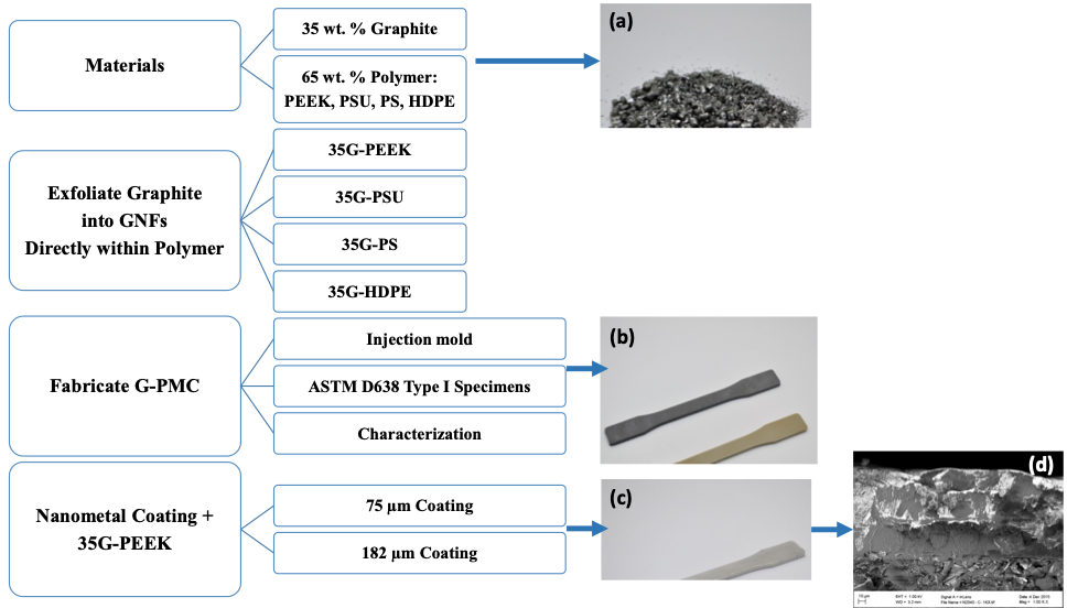
Figure 1: Experimental method schematic diagram and (a) dry-blended graphite and polymer resin, (b) Injection molded ASTM specimens (black is 35G-PEEK and amber is PEEK), (c) Nanometal coated 35G-PEEK injection molded specimen, and (d) SEM image of Nanometal coating on 35G-PEEK.
For electrical conductivity and sensor testing, PSU was selected as the matrix for the G-PMC, based on preliminary data collected comparing different matrices. From this preliminary data, G-PSU incurred the highest electrical conductivity compared with the other matrices tested. The sample preparation is the same as previously described, except two concentrations of graphite were selected to be exfoliated within PSU, including 20 and 40 wt. %, labelled 20G-PSU and 40G-PSU. Below 20 wt. %, electrical conductivity of G-PSU was minimal, and above 40 wt. %, melt-processing became more difficult. Thus, the lower and upper limits used in this study were 20 and 40 wt. % GNFs in PSU.
2.2 Characterization
2.2.1 Morphology and Mechanical Properties
The morphology and mechanical properties of each G-PMC and the corresponding base polymer were investigated. The morphology was viewed using a field emission scanning electron microscope (Zeiss Sigma FESEM with Oxford EDS, operated at 5kV or 20 kV) to verify graphite exfoliation into a distribution of graphene, few-layer graphene, and multi-layer graphene, and to view GNF-matrix interaction. Samples were prepared by cryogenic fracture, mounted on typical aluminum studs with carbon tape, and stored in a vacuum sealed container prior to viewing on the SEM. A 5 nm gold coating was applied to HDPE and PS samples.
Tensile mechanical properties were measured for 35G-PEEK, 35G-PSU, 35G-PS, and 35G-HDPE using a MTS Q Test/25 universal testing machine with an extensometer mounted to the specimen, according to ASTM D638. Type 1 tensile specimens were tested at a cross-head speed of 5 mm/min until failure. A minimum of 5 specimens per sample were tested and data averaged, according to the ASTM standard. The Young’s modulus in tension is reported. Tensile properties are consistent from batch to batch, as the batch size is quite large, and more than one batch has been tested for each G-PMC.
Flexural mechanical properties were measured for PEEK, 35G-PEEK, 35G-PEEK + Nanometal 75 µm, and 35G-PEEK + Nanometal 182 µm using a MTS Q Test/25 universal testing machine, according to ASTM D 790. A minimum of five specimens per sample were tested at a cross-head rate of 1.58 mm/min until 5 % strain and data averaged, following the ASTM standard. Flexural properties are consistent from batch to batch, as the batch size is quite large, and more than one batch has been tested for each G-PMC.
2.2.2 Electrical Conductivity and Sensors
Electrical conductivity was determined by using a Keithley 2450 source measure unit, according to ASTM standard D4496-13. Electric current at different potentials was measured for 20G-PSU and 40G-PSU samples (5 specimens per sample were tested, according to the ASTM). Due to the potential for structural damage resulting from high current, the test was conducted up to 20 volts potential. Conductivity as a function of voltage is presented for 20G-PSU and 40G-PSU.
The sensor capability of G-PSU samples was tested by cyclically loading and unloading specimens in 3-point flexural loading using an Instron 5982 universal testing system while simultaneously monitoring current as a function of time under a potential of 10 volts using a Keithley 2450 source measure unit. Specimens (ASTM D 638 Type I) were loaded to a maximum stress of 25 N over five cycles, while remaining within the elastic region for these composites. Specimens were also loaded to 80 N over four cycles to investigate the effect of loading beyond the elastic region. Prior to the test start, specimens were preloaded to 10 N at a loading rate of 2.5 mm/sec, followed by the test loading rate of 1 mm/min to reach 25 N and 80 N. Between loading cycles, specimens were manually unloaded and force zeroed, which took approximately 25 seconds each time.
3.0 Results and Discussion
3.1 Morphology and Mechanical Properties
Morphology images of 35G-PEEK are shown in Figure 2, and morphology images of 35 G-PSU, 35G-PS, and 35G-HDPE are shown in Figure 3. Intimate particle-matrix interaction is seen for each G-PMC. During the exfoliation process, pristine planar surfaces are created as graphene layers are sheared from graphite, which enables very good adhesive-planar bonding between GNF and polymer. Surface crystallization of the polymer in a preferred orientation growing from the pristine GNF surface is evident for PEEK in the circled region of Figure 2 (b) and HDPE in Figure 3(c). PEEK and HDPE are both semicrystalline polymers while PSU and PS are amorphous. Size reduction of the graphite particles within each G-PMC is evident in both the c-axis dimension (shearing of graphene layers from graphite into GNFs) and in the AB direction (GNF diameter). After the exfoliation process, GNFs are reduced to nano-dimensions in the c-axis direction, and the average GNF diameter is reduced ranging from 1-10 µm, as seen in Figures 2 and 3. Further, transparent GNFs are visible in 35G-PEEK, indicating few to single layer graphene, as shown in Figure 2(c). The original diameter of the graphite particles ranged between 250 – 300 μm. Thus, fracture has occurred across the AB basal plane of graphite during uniform, high shear melt-processing, allowing for covalent bonding to occur between GNF fractured edges and certain polymer chemistries (i.e. in situ functionalization).
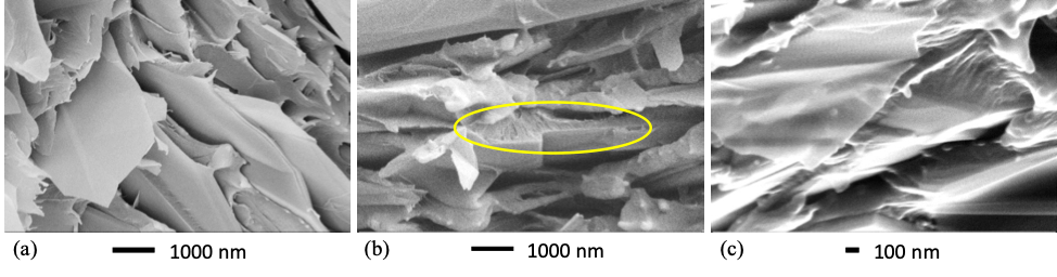
Figure 2: SEM micrographs of 35 G-PEEK at different positions and length scale
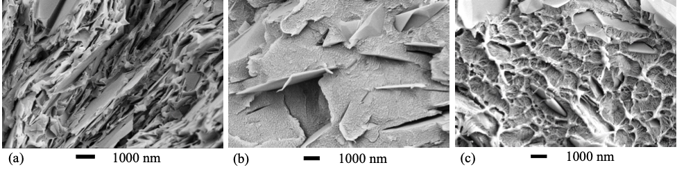
Figure 3: SEM micrographs of (a) 35G-PSU, (b) 35G-PS, and (c) 35G-HDPE
Mechanical property measurements show a significant increase in tensile elastic modulus for each G-PMC. Tensile modulus for each polymer and its G-PMC with 35 wt. % graphite well-exfoliated into GNFs is shown in Figure 3-3(a). Relative to the polymer alone, tensile modulus increases by approximately 390 %, 530 %, 260 %, and 205 % for 35G-PEEK, 35G-PSU, 35G-PS, and 35G-HDPE, respectively. The modulus increase is dependent on GNF-matrix interaction, which may be due to mechanical and/or chemical bonding, with stronger GNF-matrix interaction resulting in better mechanical properties. Certain polymer chemistries allow for edge-covalent bonding (chemical bonding) to occur between GNF edges and the matrix, providing stronger GNF-matrix interaction and better mechanical properties. For example, a polymer with a double bond to a side group in its structural repeat unit has the potential to convert to a single bond and leave an open location for chemical bonding with a GNF. For 35G-HDPE, there is no double bond in the HDPE repeat unit but mechanical interactions between GNFs and HDPE occur that cause a 205 % increase in modulus, which is likely due to surface crystallinity of HDPE on GNF surfaces. For 35G-PEEK, there is a higher percentage increase in modulus than for 35G-HDPE, which is likely due to PEEK having a double bond to an oxygen in its repeat unit that allows for edge-covalent bonding between GNFs and PEEK, as well as surface crystallinity of PEEK on GNF surfaces [19]. Additionally, the modulus of 35G-PEEK is 20 GPa, which is equivalent to 30 wt. % carbon fiber reinforced PEEK.
Tensile stress at yield increases for each G-PMC relative to the polymer alone, as shown in Figure 4 (b). The linear line between the stress value for the polymer alone and its G-PMC is not a trend line but simply connects the two data points for better visibility. The increase is not as significant as for the modulus. Thus, the strong GNF-matrix interactions significantly affect modulus but not tensile stress at yield, which may be due to a competing phenomenon. During in situ exfoliation, larger graphite particles are exfoliated into GNFs within each polymer and undergo size reduction in the c-axis direction (thickness) and in the AB direction (diameter), resulting in a distribution of the number of graphene layers within each GNF. The presence of a thicker GNF particle may act as a stress concentration, causing a reduction in strength. With a better degree of exfoliation, the size reduction of the GNF particles becomes more uniform, which will allow the strong GNF-matrix interaction to affect the strength values more significantly [19]. Furthermore, from the polymer perspective, experiments in molding are necessary to increase strength further (i.e. optimizing mold temperature), and with more efficient exfoliation, as the process is improved, polymer degradation will decrease.
The flexural modulus of PEEK, 35G-PEEK, 35G-PEEK with Nanometal coating of 75 microns, and 35G-PEEK with Nanometal coating of 182 μm is 3.8 GPa, 17 GPa, 30 GPa, and 43 GPa, respectively (Figure 5). The modulus of aluminum is approximately 69 GPa but has approximately 2.5 times greater density than the polymer. Additionally, the Nanometal coating on 35G-PEEK enhances strain to fracture, as seen in the flexural stress-strain curves in Figure 6. For 35G-PEEK with Nanometal coating of 182 µm, the Nanometal coating is able to withstand high loads and does not fracture prior to 5 % strain (test termination). Izod impact resistance of un-notched specimens for 35G-PEEK and 35G-PEEK with Nanometal coating (approximately 100 μm thickness) is 1,783 J/m and 4,700 J/m, respectively. These results suggest intimate particle-matrix interaction, as well as strong G-PMC-Nanometal coating interaction.
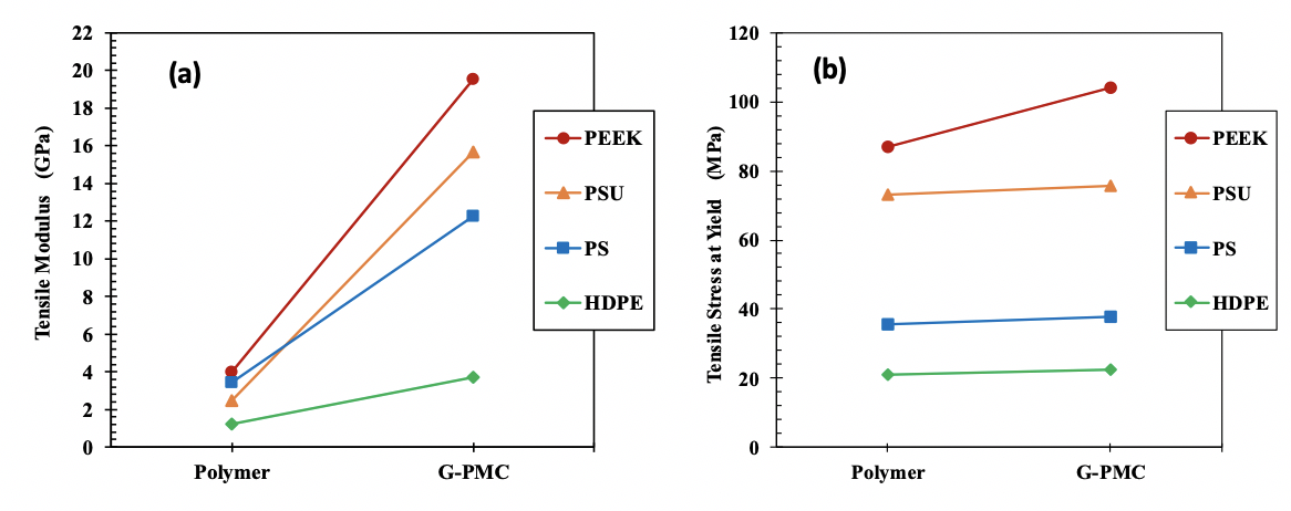
Figure 4: Tensile properties of 35 wt. % GNF enhanced G-PMCs and each polymer (a) modulus and (b) stress at yield. Lines are for improved visibility only.
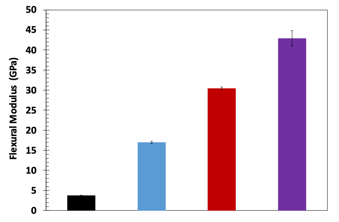
Figure 5: Flexural modulus of PEEK, 35G-PEEK, 35G-PEEK with 75 μm Nanometal coating, and 35G-PEEK with 182 μm Nanometal coating
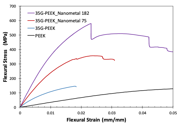
Figure 6: Flexural stress-strain curves for PEEK, 35G-PEEK, 35G-PEEK with Nanometal coating 75 μm, and 35G-PEEK with Nanometal coating 182 μm
3.2 Electrical Properties and Sensors
Electrical conductivity as a function of voltage for 20G-PSU and 40G-PSU appears in Figure 7. With an increase in GNF concentration from 20 to 40 wt. % in PSU, electrical conductivity increases by an order of magnitude. The morphology of 40G-PSU allows for more efficient electrical conductivity, as the distance between GNFs decreases with increasing GNF concentration. The easy tunability of these G-PMCs allows for optimization of functional properties, for example electrical conductivity, while simultaneously offering structural integrity.
Cyclic loading of 40G-PSU and the corresponding current versus time curves are shown in Figure 8, when loaded to 25 N (a, b) and 80 N (c, d). The current increases while under load and decreases as the load is removed, indicating that 40G-PSU is a good candidate for sensor applications. When loaded to 25 N, the stresses remain within the elastic region for the material. Loading to 80 N exceeds the material’s yield stress, however, the current response is still good. Comparing (a) and (c), the current response is slightly different due to the difference in maximum loading in that the current does not decrease fully after each loading for the sample loaded to 80 N in (c). Cyclically loading 40G-PSU to 80 N is above the material’s yield stress and likely caused plastic deformation. In application, loading should be kept within the elastic region to avoid plastic deformation. Interestingly, the mechanical response improves from the first to last loading cycle, as seen in both (b) and (d).
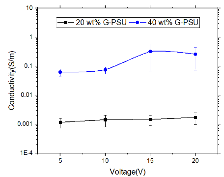
Figure 7: Electrical conductivity as a function of voltage for 20G-PSU (black) and 40G-PSU (blue)
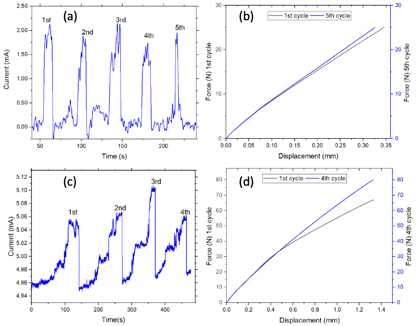
Figure 8: Sensor characterization of 40G-PSU showing current as a function of time and corresponding force versus displacement during cyclic loading to 25 N (a, b) and 80 N (c, d).
4.0 Conclusion
The general approach presented in this work will enable fabrication of a new class of high performance, lightweight G-PMCs with tuneable, multifunctional properties. The high-shear, melt processing method offers simple, versatile manufacturing; low raw materials costs; and the opportunity to enhance properties of the G-PMC with further treatment like Nanometal coatings. These materials will allow entry into a broad array of defense applications to meet current and future needs. Compared to existing solutions, materials substitution using G-PMCs offers cost and weight savings in a particular application. By reducing vehicle weight by 30 %, operational energy cost savings arise since fuel consumption will be lowered, longer service lifetime is possible since these materials are corrosion resistant, and manufacturing costs will be reduced. Improved logistics capabilities through increased range, increased payload (more ammunition per vehicle) and improved protection to the warfighter can be achieved. Some potential applications include: lightweight vehicular armor that serves as the structural component while providing ballistic protection, lightweight personnel armor that would allow reduced combat load weight and increased ammunition per soldier, lightweight UAVs that offer higher payloads and longer loitering times, lightweight munitions, lightweight tactical bridges, and sensors.
Key advantages of this in situ graphite exfoliation process to fabricate G-PMCs are that any thermoplastic polymer may be used. Very high concentrations of graphite may be added to the polymer, which are subsequently converted into GNFs; new, pristine surfaces and edges are created on exfoliated GNFs and these bond well with the surrounding molten polymer. Significant modulus enhancement occurs and GNFs impart electrical and thermal conductivity [40] and barrier resistance to small gases [41]. G-PMC properties are multifunctional and easily tuneable; and manufacturing using standard polymer processing methods may be used, including extrusion, injection molding, and additive manufacturing.
Acknowledgements
This work was sponsored by ONR-BAA: N00014-14-1-0046 and ONR-BAA: N00014-17-1-2712. Secondary funding was provided by the AMIPP Center at Rutgers University. Other inventors of the G-PMC technology include Thomas Nosker and Bernard Kear. Rutgers University students involved with the project include Arya Tewatia, Meredith Taghon, and Jamie Wooding. Electrical conductivity research was funded by TLC Products, Inc. and performed by Ali Ashraf at Rutgers University.
References
[1] Stankovich S, Dikin DA, Dommett GHB, Kohlhaas KM, Zimney EJ, Stach EA et al. Graphene-based composite materials, Nature, 442, 282-6, 2006.
[2] Hao-Bin Zhang, Wen-Ge Zheng, Yan Q, Yang Y, Ji-Wen Wang, Zhao-Hui Lu et al. Electrically conductive polyethylene terephthalate/graphene nanocomposites prepared by melt compounding, Polymer, 51, 1191-6, 2010.
[3] Sung-Chiun Shiu, Jia-Lin Tsai. Characterizing thermal and mechanical properties of graphene/epoxy nanocomposites, Composites Part B: Engineering, 56, 691-7, 2014.
[4] Hwang Y, Kim M, Kim J. Improvement of the mechanical properties and thermal conductivity of poly(ether-ether-ketone) with the addition of graphene oxide-carbon nanotube hybrid fillers, Composites. Part A, 55, 195-202, 2013.
[5] Rafiee MA, Rafiee J, Wang Z, Song H, Yu Z, Koratkar N. Enhanced mechanical properties of nanocomposites at low graphene content, ACS Nano, 3, 3884-90, 2009.
[6] Potts JR, Dreyer DR, Bielawski CW, Ruoff RS. Graphene-based polymer nanocomposites, Polymer, 52, 5-25, 2011.
[7] Potts JR, Lee SH, Alam TM, An J, Stoller MD, Piner RD et al. Thermomechanical properties of chemically modified graphene/poly(methyl methacrylate) composites made by in situ polymerization, Carbon, 49, 2615-23, 2011.
[8] Song P, Cao Z, Cai Y, Zhao L, Fang Z, Fu S. Fabrication of exfoliated graphene-based polypropylene nanocomposites with enhanced mechanical and thermal properties, Polymer, 52, 4001-10, 2011.
[9] Wakabayashi K, Pierre C, Dikin DA, Ruoff RS, Ramanathan T, Brinson LC et al. Polymer−Graphite Nanocomposites: Effective Dispersion and Major Property Enhancement via Solid-State Shear Pulverization, Macromolecules, 41, 1905-8, 2008.
[10] Gong L, Yin B, Li L, Yang M. Nylon-6/Graphene composites modified through polymeric modification of graphene, Composites Part B: Engineering, 73, 49-56, 2015.
[11] Wang J, Xu C, Hu H, Wan L, Chen R, Zheng H et al. Synthesis, mechanical, and barrier properties of LDPE/graphene nanocomposites using vinyl triethoxysilane as a coupling agent, Journal of Nanoparticle Research, 13, 869-78, 2011.
[12] Ha HW, Choudhury A, Kamal T, Kim D, Park S. Effect of chemical modification of graphene on mechanical, electrical, and thermal properties of polyimide/graphene nanocomposites, ACS Applied Materials & Interfaces, 4, 4623-30, 2012.
[13] Satti A, Larpent P, Gun'Ko Y. Improvement of mechanical properties of graphene oxide/poly(allylamine) composites by chemical crosslinking, Carbon, 48, 3376-81, 2010.
[14] Wang Y, Yang C, Mai Y, Zhang Y. Effect of non-covalent functionalisation on thermal and mechanical properties of graphene-polymer nanocomposites, Carbon, 102, 311-8, 2016.
[15] Nadiv R, Shtein M, Buzaglo M, Peretz-Damari S, Kovalchuk A, Wang T et al. Graphene nanoribbon – Polymer composites: The critical role of edge functionalization, Carbon, 99, 444-50, 2016.
[16] J.K. Lynch-Branzoi, T.J. Nosker, B.K. Kear, A. Tewatia, M. Taghon, J. Wooding. Lightweight, High Performance Polymer Composites for Modern Engineering Applications, Advanced Materials: TechConnect Briefs, 1, 192-5, 2018.
[17] Nosker TJ, Lynch JK, Kear B, Hendrix J, Chiu G. In Situ Exfoliation Method to Fabricate a Graphene-Reinforced Polymer Matrix Composite. US 20160083552. 2016.
[18] Nosker TJ, Lynch JK, Hendrix J, Kear BH, Chiu G, Tse S. In Situ Exfoliation Method to Fabricate a Graphene-Reinforced Polymer Matrix Composite. US 9,896,565. 2018.
[19] Lynch-Branzoi JK, Ashraf A, Tewatia A, Taghon M, Wooding J, Hendrix J et al. Shear exfoliation of graphite into graphene nanoflakes directly within polyetheretherketone and a spectroscopic study of this high modulus, lightweight nanocomposite. Composites Part B: Engineering 2020;188:107842.
[20] Chen Y, Zou H, Liang M. Non-isothermal crystallization study of in-situ exfoliated graphite filled nylon 6 composites, Journal of Polymer Research, 21, 2014.
[21] Zhou S, Lei Y, Zou H, Liang M. High thermally conducting composites obtained via in situ exfoliation process of expandable graphite filled polyamide 6, Polymer Composites, 34, 1816-23, 2013.
[22] Zhou S, Yu L, Song X, Chang J, Zou H, Liang M. Preparation of highly thermally conducting polyamide 6/graphite composites via low-temperature in situ expansion, J Appl Polymer Sci, 131, 2014.
[23] Feng Z, Zuo H, Hu J, Yu B, Ning N, Tian M et al. In Situ Exfoliation of Graphite into Graphene Nanosheets in Elastomer Composites Based on Diels-Alder Reaction during Melt Blending, Industrial and Engineering Chemistry Research, 58, 13182-9, 2019.
[24] Li Y, Zhang H, Crespo M, Porwal H, Picot O, Santagiuliana G et al. In Situ Exfoliation of Graphene in Epoxy Resins: A Facile Strategy to Efficient and Large Scale Graphene Nanocomposites, ACS Applied Materials and Interfaces, 8, 24112-22, 2016.
[25] Kim SR, Poostforush M, Kim JH, Lee SG. Thermal diffusivity of in-situ exfoliated graphite intercalated compound/polyamide and graphite/polyamide composites, Express Polymer Letters, 6, 476-84, 2012.
[26] Lee JW, Lee JU, Jo JW, Bae S, Kim KT, Jo WH. In-situ preparation of graphene/poly(styrenesulfonic acid-graft-polyaniline) nanocomposite via direct exfoliation of graphite for supercapacitor application, Carbon, 105, 191-8, 2016.
[27] Polakova L, Sedlakova Z, Ecorchard P, Pavlova E, Peter J, Paruzel B et al. Poly(meth)acrylate nanocomposite membranes containing in situ exfoliated graphene platelets: Synthesis, characterization and gas barrier properties, European Polymer Journal, 94, 431-45, 2017.
[28] Hassan M, Reddy KR, Haque E, Minett AI, Gomes VG. High-yield aqueous phase exfoliation of graphene for facile nanocomposite synthesis via emulsion polymerization, J Colloid Interface Sci, 410, 43-51, 2013.
[29] Tsai M, Tseng I, Huang Y, Yu H, Chang P. Transparent Polyimide Film with Improved Water and Oxygen Barrier Property by In-Situ Exfoliating Graphite, Advanced Engineering Materials, 18, 582-90, 2016.
[30] Wei P, Cui S, Bai S. In situ exfoliation of graphite in solid phase for fabrication of graphene/polyamide-6 composites, Composites Science and Technology, 153, 151-9, 2017.
[31] Emrich R. Nanometal/polymer hybrid material makes lighter, stronger snowboard bindings, Advanced Materials and Processes, 169, 50-1, 2011.
[32] Erb U, Palumbo G, Jeong D, Kim S, Aust KT. Grain Size Effects in Nanocrystalline Electrodeposits. Processing and Properties of Structural Nanomaterials: Proceedings of Symposia held at Materials Science and Technology 2003 Meeting, November 9, 2003 - November 12, Minerals, Metals and Materials Society, 2003.
[33] Gonzalez P. Electroplate alternatives to hard chrome: Nanocrystalline metals and alloys. National Association for Surface Finishing Annual Conference and Trade Show 2010, SUR/FIN 2010, June 14, 2010 - June 17, National Association for Surface Finishing, 2010.
[34] Heard R, Erb U, Palumbo G. Exploiting Hall-Petch Strengthening for Sustainability. 2008 Materials Science and Technology Conference, MS and T'08, October 5, 2008 - October 9, American Ceramic Society, 2009.
[35] Lindsay JH. Canadian company is engineering innovative materials for the future of metal finishing, Plating and Surface Finishing, 91, 7-9, 2004.
[36] Palumbo G, Gonzalez F, Tomantschger K, Erb U, Aust KT. Nanotechnology opportunities for electroplating industries, Plating and Surface Finishing, 90, 36-45, 2003.
[37] Nagarajan N, Kowpak T, Tomantschger K, Gonzalez F, Neacsu M, Ronis T et al. NanoMetal Polymer Hybrids Oberflachen technik Journal, Jahrbuch Oberflachentechnik, 67, 2011.
[38] Integran Technologies. Nanovate. https://www.integran.com/what-is-nanovate-technology, 2020.
[39] Integran Technologies. Ultralightweight Parts with Nanovate Plating on Plastics. 2016;4.
[40] Ashraf A, Jani N, Farmer F, Lynch-Branzoi JK. Non-Destructive Investigation of Dispersion, Bonding, and Thermal Properties of Emerging Polymer Nanocomposites Using Close-Up Lens Assisted Infrared Thermography, MRS Advances, 1-8, 2020.
[41] Lynch-Branzoi J, Nosker T, Kear B, Chang C. Use of Graphene-Polymer Composites to Improve Barrier Resistance of Polymers to Liquid and Gas Permeants. US WO/2019/143662. 2019.